
A practical breakdown of Mobile Substation components — transformer, HV/MV switchgear, protection relay, auxiliary power, cable set, and trailer — covering ratings, interfaces, and IEC/IEEE compliance for utility and infrastructure projects.
TL;DR — What you need to know
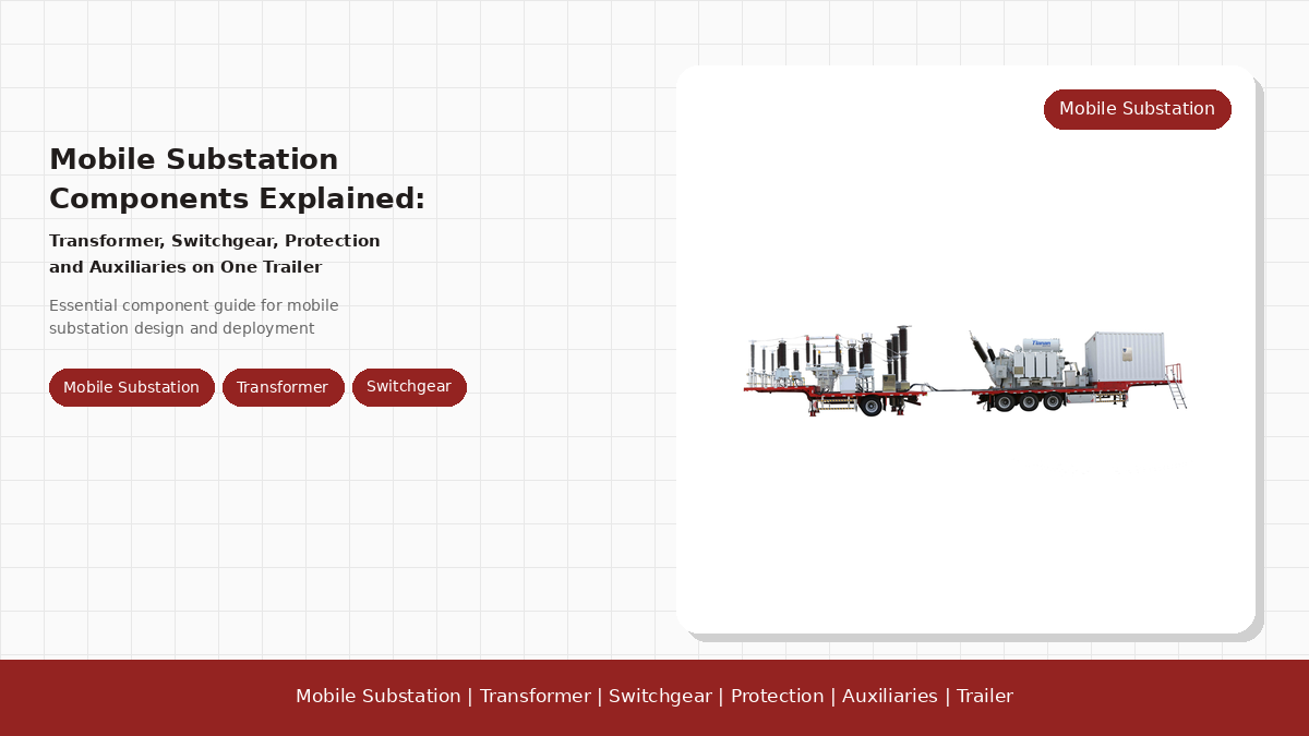
- A mobile substation packages six functional blocks on one or more trailers.Transformer, Hv Switchgear, MV switchgear, protection panel, auxiliary systems, and the trailer itself — each block is sized, tested, and documented against the same IEC standard that applies to its stationary equivalent.
- The transformer and the switchgear are built to the same IEC standards as fixed substations. IEC 60076 for the transformer, IEC 62271 for the switchgear, IEC 61869 for instrument transformers. The mobile-specific work is in the trailer and the cable interface.
- Common ratings span 0.5 MVA to 25 MVA with primary voltages from 11 kV up to 132 kV. Larger ratings split across two trailers.
- Deployment time is hours, not months. Once the trailer is on site, an experienced crew can jack, earth, terminate, and energize within a single working day.
- The transformer–switchgear interface is the most common source of defects. A supplier with in-house transformer plus switchgear production is usually a lower-risk partner for utility-scale export projects.

Why the Component Breakdown Matters Before the RFQ
If you are evaluating a mobile substation for a utility, a mining concession, or a grid contingency program, the buying decision rarely happens at the trailer level. It happens at the component level: which transformer rating, switchgear interface, protection scope, compliance declaration. A mobile substation that looks like a single line on the buyer's side is in fact six functional blocks on the supplier's side, each governed by its own IEC standard.
The reason this matters is how mobile substations fail. A fixed substation fails inside a building the utility maintains; a mobile substation fails on a roadside or in a mining pit, with a smaller crew and a faster clock. The component that fails most often is the interface between two blocks: bushing, cable termination, earthing connection. These are where standards overlap, which is why a supplier with both national-standard drafting credentials and in-house transformer plus switchgear capability is the lower-risk choice.
The single biggest rule of mobile substation sourcing: specify the interfaces first, not the trailer. The bushing–switchgear interface, the cable–panel interface, and the trailer–ground interface are where post-shipment defects cluster. Once those are locked, the component selection is mostly mechanical.
This article walks through the six functional blocks in the order a buyer's RFQ typically locks them, with the IEC standard, the rating band, and the interface that connects each block to the next. The intent is not to design a mobile substation from a browser — the buyer still needs a supplier-led coordination study — but to make the RFQ conversation about the right things at the right time.
The Power Transformer: The Anchor Component
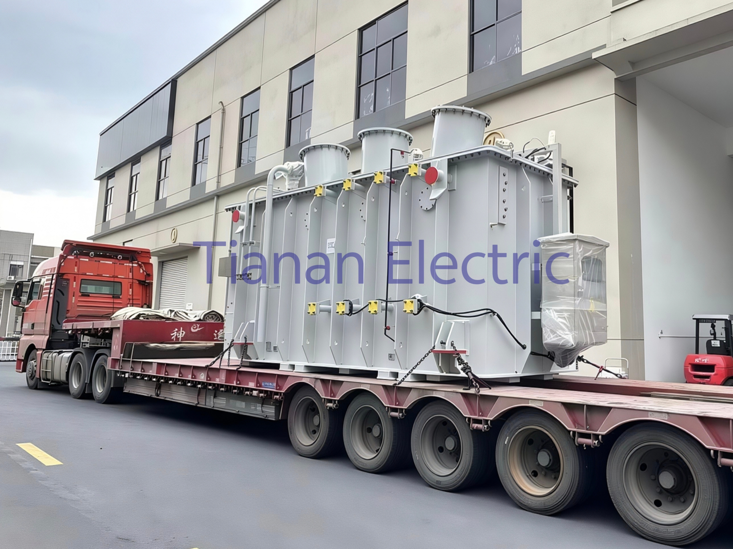
The power transformer is the anchor component, physically and economically. It sits at the trailer's centre of mass, accounts for the largest share of total weight, and sets the rating for every other block. The transformer is built against IEC 60076 — the mobile-specific work is in the mounting (anti-vibration pads, lift points), oil containment (bunded tray to catch a leak), and the coolers (radiators that fold or detach before the trailer moves).
Ratings typically span 0.5 MVA to 25 MVA. Below 0.5 MVA the buyer is looking at a skid-mounted pad-mount transformer; above 25 MVA the trailer gross vehicle weight exceeds the road-transport envelope of most destination countries, and the design splits across two trailers. Primary voltage sits between 11 kV and 132 kV; secondary voltage is configured for the load (0.4 kV for direct industrial loads, 6.6 kV or 11 kV for distribution feeders, 33 kV for sub-transmission bridging).
The vector group, impedance percentage, and tap-changer range are the next three parameters the RFQ has to lock. The vector group (typically Dyn11 for distribution, YNyn0 for transmission bridging) sets phase displacement between primary and secondary. The impedance percentage (typically 6% to 12% for distribution) sets the fault level the downstream switchgear must break. The tap-changer range sets how the mobile substation handles voltage variation on the incoming grid.
The transformer rule for mobile units: the transformer rating sets the gross vehicle weight, the trailer impedance sets the downstream fault level, and the vector group sets the SCADA mapping. Get all three right in the RFQ and the switchgear selection follows.
Buyers who skip the impedance conversation usually find out about it at the factory acceptance test, when the short-circuit test on the switchgear fails because the impedance is too low and the fault current is too high. Buyers who skip the tap-changer conversation usually find out at the site commissioning, when the mobile substation cannot hold voltage against a weak grid. Both are recoverable but both delay the energisation date.
HV Switchgear: The Incoming Bay
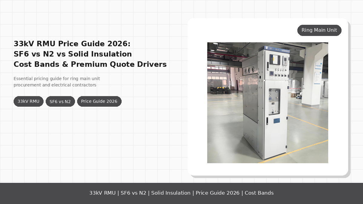
The HV switchgear is the bay connecting to the transmission or sub-transmission line being bridged. It is built against IEC 62271-1 and IEC 62271-200 (metal-clad AC switchgear for voltages above 1 kV up to 52 kV, with 62271-203 for gas-insulated variants at higher voltages). The mobile-specific work is the bay layout: it must fit within the road-transport width envelope, the disconnector must be operable from the trailer platform, and the CTs/VTs must be accessible without removing the bay.
The HV bay is line–disconnector–breaker–VT, with the option of adding a surge arrester on the incoming side (IEC 60099-4). The arrester's presence depends on the lightning exposure of the destination site — a mining pit in a dry climate usually gets away without one, a sub-transmission line in a tropical climate usually requires one. The breaker mechanism (vacuum for 11 kV to 36 kV, SF₆ for 52 kV to 145 kV) is set by voltage class, short-circuit budget, and operating-duty cycle.
A common mistake is to size the HV bay for the same short-circuit current as a fixed substation without checking the impedance contribution of the transformer. The transformer's impedance reduces the fault current the HV breaker must interrupt, letting the buyer specify a lower short-circuit rating. The IEC 62271 series lets the supplier demonstrate the lower rating at the type test. The EU Energy Infrastructure framework is the reference set most export buyers work against.
MV Switchgear: The Outgoing Bay
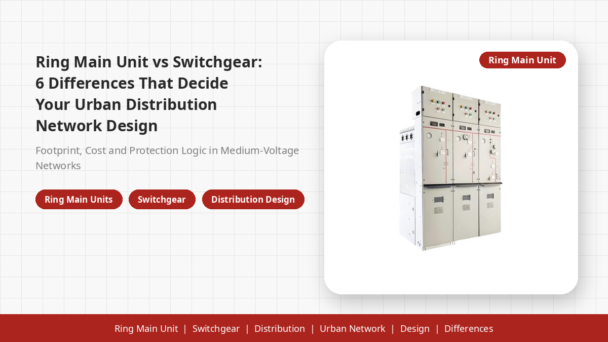
The MV switchgear is the bay that feeds the load — distribution feeders, industrial plant, mine pit, dam site. It is also built against IEC 62271-200, but typically at a lower voltage class than the HV bay (12 kV to 36 kV). The bay count drives the trailer length: a single-outgoing substation fits on a short trailer, a four-outgoing needs a longer trailer, and an eight-outgoing usually splits across two trailers.
The MV bay configuration is breaker–CT–VT–cable termination, repeated per outgoing circuit. Cable terminations are most exposed to site conditions, so the bay uses fully shrouded terminations meeting IEC 62271-200's IP rating and the relevant arc-resistant class. Arc-resistant panels are worth considering for any substation operated by a small crew without full PPE. Reference: NEMA switchgear standards provide the North American framework for equivalent panels.
The instrument transformers (CTs and VTs) on the MV bay are built against IEC 61869, the harmonised standard that replaced the older IEC 60044 series. CT ratio, burden, accuracy class, and polarity are the parameters the buyer's protection study locks — they must be on the RFQ before the MV bay is quoted, because changing them after the bay is built means a re-test on every CT.
Protection and Control: The Panel That Ties the Blocks Together
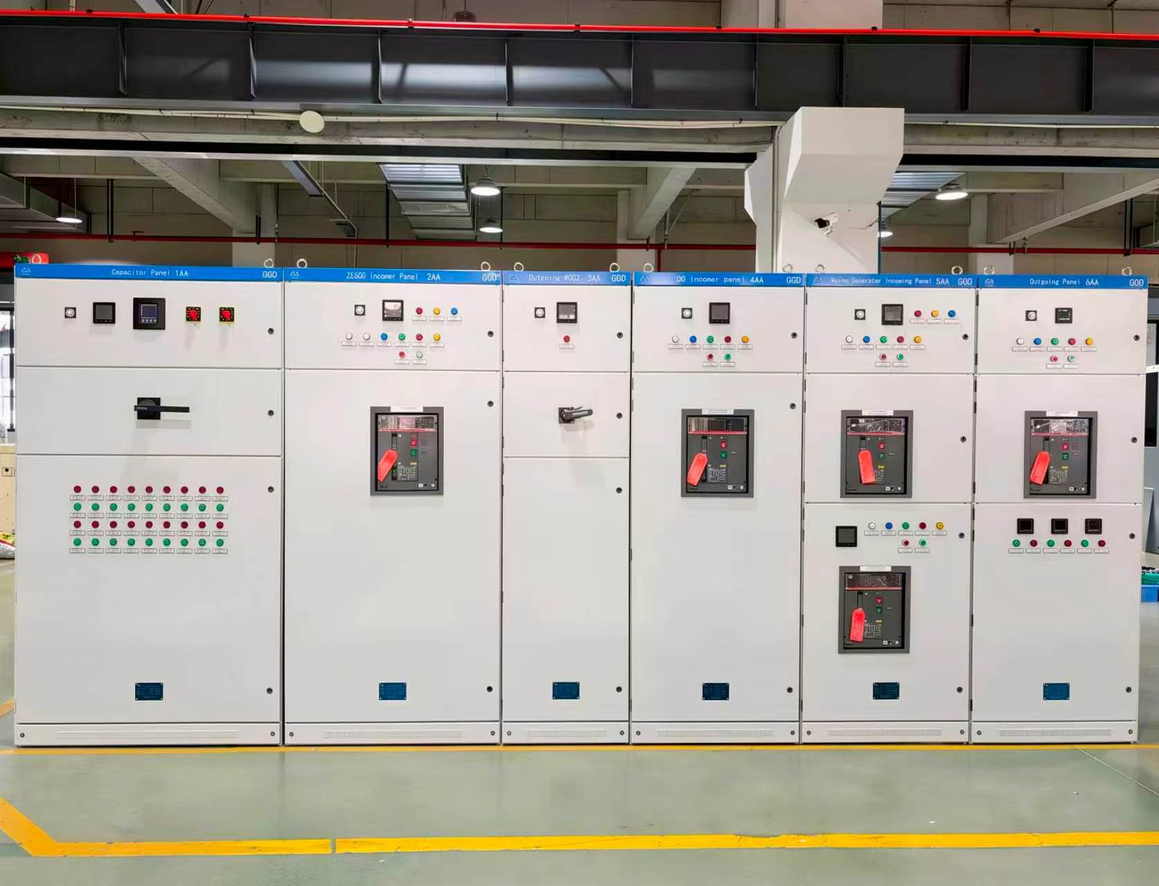
The protection and control panel turns a collection of switchgear bays into a coordinated system. Numerical relays handle differential protection on the transformer (87T), overcurrent and earth-fault on each MV feeder (50/51, 50N/51N), distance or line protection on the HV side (21), breaker failure protection (50BF), and the SCADA gateway. The panel is fed from a battery-backed DC supply and housed in the cable compartment at the trailer centre.
The SCADA protocol is one of the most common sources of integration friction on export projects. IEC 61850 is the international default for new substations; DNP3 dominates North American utility networks; IEC 60870-5-104 is the European default at the control-centre interface. A mobile substation designed for export usually ships with an IEC 61850 gateway that can map to DNP3 or IEC 60870-5-104, but the mapping work must be in the RFQ scope from day one.
The coordination study is what makes the panel work. The buyer provides short-circuit level, load current per feeder, transformer impedance, and upstream protection operating time. The panel is configured so a fault on any MV feeder is cleared by that bay's own breaker without tripping the transformer differential or HV breaker. Configuration is locked at the factory and verified at the FAT and SAT. CIGRE working-group guidelines are the most-cited reference for transformer differential and overcurrent coordination studies on export projects.
The protection rule: the panel's job is to make the other five blocks safe to operate, not to add a feature list. A correctly configured panel with three functions is more useful than an over-specified panel with thirty functions, because the operating crew can actually understand it during an incident.
Auxiliary Systems: The Hidden Half of the Substation
The auxiliary systems are the easiest block to under-specify and the most expensive to retrofit. They include the AC station-service supply (small auxiliary transformer fed from the MV side), the DC battery and charger (110 V or 220 V DC, sized for eight hours), the cable set (HV and MV cables to incoming line and load), the earthing set (copper braid to site ground grid), the lighting and small-power distribution, and fire detection for the transformer bay.
The earthing set is the auxiliary component with the highest safety stakes. The site ground grid has to be designed against IEEE 80 for North American substations; equivalent IEC practices apply elsewhere. The trailer frame must bond to the grid with a short, low-impedance connection carrying the full short-circuit current until protection clears. A loose or undersized earthing braid is the most common post-shipment defect.
The cable set is the auxiliary component with the highest procurement stakes. A mobile substation ships with defined length of HV and MV cable (typically 25 to 50 metres per circuit), terminated and tested at the factory, coiled on the trailer for shipment. Cable type, cross-section, and termination class must be on the RFQ before the trailer is built, because changing them after the cable compartments are welded means a re-design.
The Trailer and Transport Envelope
The trailer is the mobile-specific block that has the least overlap with fixed-substation engineering and the most overlap with the destination country's road-transport regulations. The axle count, the axle load, the gross vehicle weight, the height, the width, and the towing class all have to clear the destination country's road-transport envelope before the electrical design is finalised. A mobile substation that satisfies IEC 62271 and IEC 60076 but exceeds the destination country's road-transport envelope is unshippable.
The mechanical design on the trailer includes the outriggers (hydraulic jacks that lift the trailer off the transport wheels), the towing gear (fifth-wheel or tow-bar depending on destination country), the lifting points (for crane deployment), the bunded oil tray under the transformer (to catch a leak), the cable compartments (where the cable set is coiled for shipment), and the earthing pads.
Seismic design is an option buyers in Asia, the Middle East, and South America ask for, even on mobile substations not deployed in a seismic zone. It follows IEEE 693 for North American projects or the local equivalent, and drives the trailer's mechanical design (transformer mounting, switchgear bracing, outrigger anchoring) more than the electrical design. A non-seismic-rated trailer can be deployed in a seismic zone, but the insurer charges a premium.
The trailer rule: the trailer envelope drives the electrical design, not the other way around. A mobile substation's rating is set by what the destination road can carry, not by what the transformer can deliver. Buyers who specify the rating first and the trailer second usually end up with a trailer that does not clear the road.
How the Blocks Compose Into a System
The six blocks — transformer, HV switchgear, MV switchgear, protection panel, auxiliaries, trailer — are designed separately but commissioned together. The factory acceptance test (FAT) is where the composition happens: the supplier powers the trailer from a test supply, closes the HV breaker, energises the transformer, closes the MV breakers, and verifies that the protection panel trips the right breaker for each simulated fault. The FAT takes a working week for a typical mobile substation, and the FAT report is the document the buyer's witness engineer signs before the trailer is shipped.
The site acceptance test (SAT) verifies the composition against the real grid. The trailer is towed to site, jacked up, earthed, terminated to incoming line and load, energised. The SAT is shorter than the FAT (a working day for an experienced crew) but it is where protection coordination is finally verified against the real short-circuit level, grid impedance, and operating crew. A trailer that passes FAT but fails SAT usually has a coordination issue.
The handover separates a working mobile substation from a working mobile substation program. The buyer takes ownership of the trailer, the documentation (as-built drawings, test reports, coordination study, operation and maintenance manual), and the spare-part list. A mobile substation handed over with complete documentation works; one with a partial pack spends its first year in the maintenance bay.
Component Comparison Table
| Block | Function | Governing standard | Typical rating / range | Mobile-specific work |
|---|---|---|---|---|
| Power transformer | Voltage step-up or step-down | IEC 60076 | 0.5 to 25 MVA; 11 kV to 132 kV primary | Anti-vibration mounts, oil bund, fold-flat radiators |
| HV switchgear (incoming bay) | Connect, protect, disconnect incoming line | IEC 62271-1, IEC 62271-200 | 36 kV to 145 kV; 16 kA to 40 kA short-circuit | Truck-fit bay, ground-level operable |
| MV switchgear (outgoing bay) | Feed and protect outgoing circuits | IEC 62271-200 | 12 kV to 36 kV; 25 kA to 31.5 kA short-circuit | Arc-resistant option, fully shrouded terminations |
| Instrument transformers | Current and voltage sensing for protection | IEC 61869 | CT/VT per bay | Accessible without removing bay |
| Protection and control panel | Trip, meter, SCADA | IEC 60255 (relays), IEC 61850 / DNP3 (gateway) | Numerical, IEC 61850 default | Battery-backed DC, pre-configured against coordination study |
| Auxiliary systems | Station service, DC battery, cables, earthing, lighting | IEC 61936-1, IEEE 80 for grounding | 110 V DC or 220 V DC; 8-hour battery reserve | Bunded oil tray, coiled cable set, earthing pads |
| Trailer and outriggers | Road transport, deployment, levelling | Destination-country road-transport regulations; IEEE 693 optional | Two to four axles, GVW within envelope | Hydraulic outriggers, towing gear, lifting eyes |
Matching the Mobile Substation to the Project
The component composition is set by the project, not the supplier's catalog. A utility contingency program typically wants 10 MVA to 25 MVA on a two-axle trailer with full IEC 61850 SCADA and arc-resistant panels. A mining program wants 2 MVA to 5 MVA on a three-axle trailer with simplified protection and on-load tap-changer. A dam site or flood-relief program wants 1 MVA to 2.5 MVA on a two-axle trailer with conventional protection. EU projects align with CENELEC harmonised standards.
The supplier's role is to map the project to the component composition and verify that it clears the destination country's compliance scope. A supplier with both vehicle-mounted mobile substation range experience and a drafting seat on the relevant Chinese national standards is the lower-risk choice for export projects, because the supplier has the in-house evidence (type test reports, design verification, coordination studies) to back the compliance declaration.
The buyer's role is to pin down project requirements at RFQ: rating, voltage class, impedance, vector group, protection scope, SCADA protocol, trailer envelope, compliance scope, and road-transport envelope. A buyer who pins down all of these at RFQ usually gets a quote in two weeks and a delivered trailer in three to five months. The IEEE Standards Association catalog is the most comprehensive reference for North American compliance.
Need a Mobile Substation Quote?
Send us your rating, primary and secondary voltage, vector group, impedance, protection scope, SCADA protocol, and destination country. We will respond with a per-block component breakdown, a compliance declaration, and a trailer envelope check.
Request Mobile Substation Quote →Frequently Asked Questions
What are the main components of a mobile substation?
A mobile substation packages six functional blocks on one or more trailers: a power transformer, HV switchgear (incoming), MV switchgear (outgoing), protection and control panel, auxiliary systems, and the trailer itself with hydraulic jacks and towing gear. Each block is sized, tested, and documented against the same IEC standard that applies to its stationary equivalent.
How is a mobile substation different from a prefabricated substation?
A prefabricated substation is built into a steel enclosure and stays in place once commissioned; a mobile substation is built on a wheeled trailer with towing gear, hydraulic outriggers, and lifting points, so it can be relocated in hours rather than months. The functional blocks (transformer, switchgear, protection) are essentially the same as a fixed substation, but the mechanical design, the cable interface, and the earthing arrangement are re-engineered for road transport and rapid deployment.
What IEC standards apply to mobile substation components?
The transformer falls under IEC 60076 (power transformers), the HV switchgear under IEC 62271-1 and IEC 62271-200 (metal-clad AC switchgear), the instrument transformers under IEC 61869, the surge arresters under IEC 60099-4, and the overall system is typically built against the project specification that references IEC 61936-1 (power installations exceeding 1 kV AC). Mobile substations also need the trailer to meet road-transport regulations in the destination country, which is independent of the IEC electrical scope.
What rating range do mobile substations cover?
Common ratings span 0.5 MVA to 25 MVA on the power transformer, with primary voltages from 11 kV up to 132 kV and secondary voltages at 0.4 kV, 6.6 kV, 11 kV, or 33 kV depending on the load. Larger ratings are possible on multi-trailer split designs, where the transformer rides on one trailer and the switchgear on another.
How long does it take to deploy a mobile substation on site?
Once the trailer is on site, a mobile substation can be lowered off the transport wheels, jacked up on outriggers, earthed, and energised within a single working day for an experienced crew. Cable termination, protection relay configuration, and load transfer add another day or two depending on the system. The deployment time is the main reason utilities keep mobile substations in their contingency fleet — they buy hours instead of months.
What protection relay scope ships with a mobile substation?
A typical mobile substation ships with a numerical protection panel covering differential protection on the transformer, overcurrent and earth-fault on each MV feeder, distance or line protection on the HV side if required, breaker control, and a SCADA gateway (IEC 61850 or DNP3 depending on the utility). Battery-backed DC supply keeps the relays and trip coils alive through an AC outage, and the panel is pre-configured against the project's coordination study so commissioning on site is mostly verification.
Who supplies mobile substations for utility projects?
Mobile substations are typically supplied by transformer manufacturers who also build switchgear, or by switchgear manufacturers who integrate a purchased transformer, with system integration handled in-house. A supplier with both an active role in standards drafting and in-house transformer plus switchgear capability is usually the safer choice for export projects, because the interface between the transformer and the switchgear is the most common source of post-shipment defects.